
What Is an Air Circuit Breaker Protection Relay?
An air circuit breaker protection relay is the decision-making layer behind a low-voltage power switchboard. It monitors current through sensors, identifies faults, and commands the breaker to trip. In a 400-volt distribution panel, that response may prevent a loose terminal from becoming an arc flash, equipment fire, or prolonged outage.
The need is growing. The International Energy Agency’s Electricity 2024 report projects global electricity demand will rise by about 4% annually through 2025. More demand places greater pressure on aging networks, factories, data centers, and renewable-energy connections. Meanwhile, IEC 60947-2 defines important requirements for low-voltage circuit breakers, including protection performance and testing. These standards matter, but field conditions can be less tidy. Dust, heat, incorrect settings, and poor coordination still undermine reliable protection.
Protection engineer J. Lewis Blackburn described the purpose clearly: “Protective relaying is the art and science of applying relays and associated equipment.” That idea remains practical today. A modern air circuit breaker protection relay must distinguish overloads from short circuits, coordinate with downstream devices, and record useful trip information. A delay of a few milliseconds can affect selectivity. A wrong pickup setting can leave conductors dangerously exposed. This article examines how the relay works, where it fits inside an air circuit breaker, and which technical details deserve closer review. Some installations still rely on factory settings without enough site verification. That is a weakness worth questioning.

What Is an Air Circuit Breaker Protection Relay?
What Is an Air Circuit Breaker Protection Relay?
An air circuit breaker protection relay is the decision-making part of an air circuit breaker. It monitors electrical current through sensors, often current transformers, and detects unsafe conditions. When current exceeds a selected limit, the relay sends a trip signal to open the breaker. The breaker then separates its contacts and stops the fault current. The relay usually does not interrupt the current itself. It gives the command.
Protection may include long-time overload, short-time fault, instantaneous short-circuit, and ground-fault functions. Each function responds at a different speed. For example, a motor starting normally may draw high current briefly. The relay should allow that start without unwanted tripping. A damaged cable, however, may require rapid disconnection. Settings must match the conductor size, equipment rating, and coordination plan.
Small details matter. During field testing, technicians inspect terminals, sensor wiring, trip circuits, and stored event records. A loose connection can create misleading measurements. Incorrect settings can also leave equipment exposed, even when the relay appears healthy. Testing with approved injection equipment helps verify pickup current and operating time. The answer is not perfectly simple. Heat, dust, aging components, and poor maintenance can change performance. A careful engineer reviews actual load behavior instead of copying settings from another installation.
| Protection Relay Dimension | Typical Setting or Rating | Protection Function | Practical Notes |
|---|---|---|---|
| Long-Time Overcurrent Protection | Approximately 0.4–1.0 × rated current | Protects conductors and equipment from sustained overloads that can cause excessive heating. | The pickup value should be coordinated with the continuous load and the allowable ampacity of the connected conductors. |
| Long-Time Delay | Commonly adjustable from several seconds to several minutes | Allows temporary overloads, motor starting current, and transformer energization current without unnecessary tripping. | The exact delay depends on the protection unit and the required coordination with downstream devices. |
| Short-Time Overcurrent Protection | Approximately 2–10 × rated current | Detects high-current faults while allowing selective coordination with downstream circuit breakers. | Short-time protection may operate with a definite-time delay or an I²t characteristic. |
| Short-Time Delay | Typically 0–0.5 seconds | Provides a controlled delay so a downstream protective device can clear a fault first. | The delay must remain short enough to limit thermal and mechanical stress during a fault. |
| Instantaneous Overcurrent Protection | Often adjustable from about 2–15 × rated current | Trips the air circuit breaker rapidly during severe short-circuit conditions. | Instantaneous protection generally has no intentional time delay and may be disabled only when the protection study permits it. |
| Ground-Fault Protection | Commonly adjustable from about 0.2–1.0 × rated current | Detects current returning through an unintended ground path and reduces the risk of equipment damage and fire. | The pickup and delay should account for system grounding, leakage current, and coordination requirements. |
| Ground-Fault Time Delay | Typically 0–0.5 seconds | Coordinates ground-fault operation with downstream protective devices. | Longer delays can improve selectivity but may increase fault exposure time. |
| Neutral Protection | Commonly 50%, 100%, or another configured fraction of phase pickup | Protects the neutral conductor when the neutral is smaller than the phase conductors or when harmonic currents are significant. | Neutral sensing and protection requirements depend on the wiring system and applicable electrical code. |
| Current Measurement | Phase and, where applicable, neutral current measurement | Provides the relay with the electrical measurements needed for overload, short-circuit, and ground-fault decisions. | Current transformers or integrated sensors must be correctly rated and installed for the system current and frequency. |
| Trip Decision Method | Pickup threshold plus time-current characteristic | Determines whether the measured current has exceeded a protection threshold for the required duration. | Digital protection units may calculate true RMS current and apply multiple protection curves. |
| Trip Output | Electronic trip command to the breaker mechanism | Activates the opening mechanism so the air circuit breaker interrupts the fault current. | The relay is the decision-making element; the circuit breaker contacts and arc-control system perform the interruption. |
| Protection Unit Power Supply | Self-powered, externally powered, or dual-supply arrangement | Supplies the relay electronics and maintains protection functions during normal operation and fault conditions. | Some units require auxiliary power for advanced features such as communication, metering, or event recording. |
| Trip Indicator | Mechanical flag, LED indication, display message, or combination | Shows that the breaker opened because of an overcurrent or ground-fault event. | The trip cause should be recorded before resetting the breaker and restoring power. |
| Event and Fault Recording | Optional; may include current, trip type, and time stamp | Supports troubleshooting, maintenance, and verification of protection performance. | Recording capability varies by protection unit and may require an auxiliary power source. |
| Communication Capability | Optional digital network connection | Allows remote monitoring of measurements, alarms, breaker status, and trip information. | Communication does not replace the local protective trip function and should be treated as a monitoring feature. |
| Selectivity and Coordination | Based on time-current settings and system fault levels | Ensures that the protective device nearest the fault operates before an upstream device whenever possible. | Coordination should be verified using a short-circuit study and time-current coordination analysis. |
| Typical Applications | Main switchboards, distribution boards, generators, and large industrial loads | Provides adjustable protection for high-current low-voltage distribution systems. | The final settings must be selected for the specific system voltage, current, fault level, load profile, and installation rules. |
Note: The values shown are common engineering ranges for low-voltage air circuit breaker protection units. Actual settings, interrupting capacity, sensor arrangement, and available functions must be confirmed from the equipment documentation and the applicable electrical standards.
Related Posts
-

Why Air Circuit Breaker Protection Relays Are Essential for Electrical Safety: Key Industry Insights
-

2026 Best DC Molded Case Circuit Breaker for Global Buyers?
-

2026 How to Choose the Right Surge Protective Device for Your Home?
-

2026 Best DC MCCB Choices for Your Electrical Needs?
-

Top 5 DC Surge Protection Devices You Need to Consider?
-
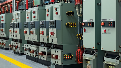
What is an Air Circuit Breaker Protection Relay?


