
Why Use a DC Contactor in Battery Systems?
Battery systems are moving from electric vehicles into homes, factories, data centers, and renewable-energy projects. The International Energy Agency reported nearly 14 million electric car sales worldwide in 2023, representing about 18% of new car sales. This growth increases demand for safer, more serviceable battery architectures. Within these systems, a dc contactor provides controlled high-current switching between the battery, inverter, charger, and load.
It is more than an electrically operated switch. A properly selected dc contactor can isolate high-voltage circuits during startup, shutdown, maintenance, or fault conditions. Pre-charge contactors also limit capacitor inrush current, helping protect inverters from damaging electrical stress. This function matters because battery packs can deliver hundreds of amperes within milliseconds. Small design choices become significant.
Safety depends on details.
IEC 60947-4-1 addresses contactor and motor-starter requirements, while UL 810A covers solid-state and hybrid switching technologies for battery applications. These standards do not replace system engineering. Engineers must evaluate voltage, continuous current, short-circuit capability, switching frequency, contact welding risk, coil power, and thermal performance. The contactor must also work reliably inside a sealed enclosure, where heat and condensation may accumulate.
The argument is not flawless: a dc contactor cannot correct poor insulation, weak monitoring, or an undersized busbar. Real installations are less tidy than laboratory diagrams. Field experience shows that connector torque, pre-charge timing, and auxiliary-contact feedback can decide whether a system starts safely. Therefore, selecting a dc contactor should be treated as a coordinated protection decision, not a simple component purchase.
What Is a DC Contactor in a Battery System?
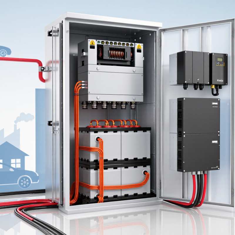
In a battery system, a DC contactor is an electrically controlled switch for connecting or disconnecting the battery’s main current path. It may sit between the battery pack and an inverter, motor, or charging circuit. A low-voltage signal energizes its coil, moving internal contacts to open or close the circuit. Not a fuse.
DC current can sustain an electrical arc when contacts separate, so a contactor must be rated for the system’s voltage and current. Its internal design may include arc-control features, such as magnetic blowouts. A contactor is not automatically able to interrupt every fault; a correctly rated fuse or other protection is still needed. This detail is easy to overlook.
Some battery systems use a precharge circuit before closing the main contactor. A resistor can limit the brief surge into an inverter’s capacitors, reducing stress on the contacts. Auxiliary contacts may report whether the main contacts appear open or closed, though they do not prove that the entire circuit is safe. In real installations, wiring, load type, and switching frequency all affect selection. A contactor can look adequately sized on paper, yet its service life may disappoint under repeated high-current switching.
| Data Dimension | Typical Data or Specification | Role in a Battery System |
|---|---|---|
| Definition | Electrically controlled high-current switch | A DC contactor connects or disconnects a battery from the main DC bus while allowing the battery-management system to control the power path. |
| Primary Function | Controlled battery isolation | It interrupts the connection during faults, maintenance, shutdown, overcurrent events, insulation faults, or emergency conditions. |
| Typical System Voltage | 12 V to 1,000 V DC, depending on system design | The contactor must be selected for the battery pack's maximum continuous voltage and any expected transient voltage. |
| Typical Continuous Current | Approximately 50 A to 600 A; higher ratings are available | The continuous-current rating should exceed the highest sustained charge or discharge current, with suitable thermal margin. |
| Breaking Capability | Specified separately from continuous-current capacity | A contactor may carry a high continuous current but have a lower safe interrupt rating. The interrupt rating must match the available battery fault current. |
| Switching Method | Normally open or normally closed main contacts | Normally open main contacts are commonly used so that the battery is isolated when the coil is de-energized. |
| Arc Control | Magnetic blowout, arc chamber, or sealed switching design | Direct current does not naturally pass through zero, so arc-control features are required to interrupt DC safely. |
| Coil Voltage | Common control voltages include 12 V, 24 V, and 48 V DC | The coil voltage must match the control supply provided by the battery-management system or auxiliary power circuit. |
| Coil Power | Higher pickup power; reduced holding power on energy-saving designs | A pull-in and hold strategy can reduce heat generation and auxiliary energy consumption during long operating periods. |
| Precharge Contactor | Lower-current contactor used with a precharge resistor | It limits inrush current when charging inverter or DC-link capacitors before the main contactor closes. |
| Main Positive Contactor | High-current contactor on the positive battery path | It provides controlled connection of the positive battery terminal to the system bus. |
| Main Negative Contactor | High-current contactor on the negative battery path | It enables two-pole isolation when the system design requires both battery conductors to be disconnected. |
| Auxiliary Contacts | Optional normally open or normally closed feedback contacts | They provide contact-position feedback so the battery-management system can verify whether the main contactor is actually open or closed. |
| Safety Monitoring | Voltage verification, weld detection, and current monitoring | The control system can compare measured bus and battery voltages to detect welded contacts, failed precharge, or an unexpected open circuit. |
| Electrical Isolation | Galvanic separation when the main contacts are open | Opening the contactor helps isolate high-voltage battery energy from downstream equipment during servicing or fault conditions. |
| Common Applications | Electric vehicles, energy-storage systems, industrial equipment, and backup power | These applications require controlled connection, rapid isolation, and protection of high-power DC circuits. |
| Key Selection Factors | Voltage, continuous current, interrupt current, temperature, environment, and coil requirements | Correct selection prevents overheating, contact welding, insulation breakdown, nuisance opening, and unsafe interruption of battery current. |
| Important Limitation | Not a replacement for a fuse or circuit breaker | A contactor provides controlled switching, while a fuse or circuit breaker provides overcurrent protection. Many battery systems require both. |
| Typical Operating Sequence | Check conditions → close precharge path → verify bus voltage → close main contactor → open precharge path | This sequence reduces capacitor inrush current and confirms that the DC bus is ready before full battery current is applied. |
Related Posts
-
10 Essential Tips for Choosing the Right Circuit Breaker Switch
-
What is the Best Electric Breaker Switch for Home Use?
-
Ultimate Guide to Choosing the Right Surge Protection Circuit Breaker for Your Needs
-

2026 Top Power Distribution Solutions for Global Buyers?
-
10 Essential Tips for Choosing the Right Miniature Circuit Breaker for Your Projects
-
What is the Best MCCB Breaker for Your Electrical Needs?


